 You guys asked for an electronics tutorial and I had a blast making one! In this introductory tutorial I will provide a massive overview while also showing how to build an AM radio on a breadboard.
We’ll learn about electricity, conductors, current, voltage, power, resistors, breadboards, LEDs, semiconductors, Ohm’s law, electromagnetic waves, microphones, carrier waves, ferrite rod antennas, integrated circuits, piezoelectric earphones, variable capacitors and a whole lot more. All the parts and a transcript follow the video below.
If you like videos like this, it would help me greatly if you’d support me on Patreon. I’ll be providing many exclusive videos there such as a Arduino programming tutorial and much more to show my gratitude.
[googleplusone]
Parts From the Video
You can buy Radio kits Cheap here : http://amzn.to/1nhCbn4
You can get large boxes of every resistors, capacitors, LEDs on Amazon and EBay. I like Joe Knows Electronics for these : http://amzn.to/1ZLjFQo
Breadboard used : http://amzn.to/1nhBD0q
MK484 IC : http://amzn.to/1ScZXwa
Tuning Capacitor : http://amzn.to/1ZLkd8K
Piezoelectric Earphone : http://amzn.to/1ZLko45
1.5V AA Battery Case Holder : http://amzn.to/1nhC36U
Antenna Coils are best bought in a kit or on EBay
Where to Place the Components on the Breadboard
100,000 ohm resistor( brown, black, yellow): I9 and J17
1,000 ohm resistor (brown, black, red): I17 and I20
0.01 microfarad capacitor (marked 103 or .01M): G9 and G15
0.1 microfarad capacitor (marked 104 or .1M): F15 and F17
0.1 microfarad capacitor (marked 104 or .1M): G17 and G22
MK484 IC: H15, H16, and H17 (flat side facing row G)
Antenna coil: J9 and G16
Tuning capacitor: F9 and F16 (only the two rightmost leads are used)
Piezoelectric earphone: F20 and F22
Negative battery wire (black): J15
Positive battery wire (red): J20
Breadboard Layout
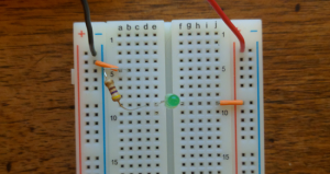
Black Negative Battery Wire : 1st post under the negative sign
Jumper Wire : 2nd post under the negative sign and A5
Resistor : B5 and D9
LED : Short wire in E9 and Long wire in F9
2nd Jumper Wire : J9 and 9th post under the positive sign
Red Positive Battery Wire : 1st post under the positive sign
Transcript from the Video
---------- What is Electricity ----------

Electricity is the movement of electrons through a conductor. More specifically electrons move towards a positive force through a good conductor.

If you connect a conductor to both ends of a battery electrons will flow from the negative to the positive terminals. This movement of electrons is known as a current.

An electrical current (I) exists when electrons move through a substance. We measure it in terms of the number of electrons that pass a point in a second. The ampere is the unit of measure for current. 1 ampere is 6.28 x 10^18 electrons passing a point per second.

An example of a good conductor would be a metal like Copper, while a bad one would be diamond. Resistance measures how easily electrons can move through a substance.

The electron shell configuration of an atom determines if something is a good conductor or not. If the outer shell can accomodate many electrons it is a good conductor. You can fit 2 electrons in the first shell. 8 in the 2nd. 18 in the 3rd. 32 in the 4th. Copper is a good conductor because it has 31 empty spaces in its 4th shell. A carbon molecule can easily fill its 4 empty spaces in its 4th shell in comparison.

---------- What is Voltage ----------

Voltage (V) is the force being applied to a current. Volts is the unit of measure for an electromotive force, which occurs when you have a build up of an excess (negative) number of electrons in one place and a shortage (positive) of electrons in another. EMF is the potential amount of charge.

You can check the voltage of a battery by switching your multimeter to the V symbol with the straight line under it. Then place a terminal on each side of the battery.

---------- What is Power ----------

Power (P) represents the work performed by an electrical current.

---------- Bring it Together ----------

If you had a water tower with a nozzle on it that released water on to a turbine which spins then : Voltage = the amount of water in the tower, Current = The amount of water passing from the nozzle, Resistance = The size of the nozzle, Power = The spinning of the turbine.

Error Fix : In the water analogy as pressure is built up in the tank the water pushes up against the walls of the tank because it has no place to go. In electronics we replace water with the build up of electrons. That accumulation is represented by voltage. As we accumulate more charges the stronger the electrostatic field becomes. Current then can be measured based on the eventual movement of those charges, or the water. I hope I explained it better now.

---------- What is a Resistor ----------

A resistor reduce the flow of current and voltage. You can figure out their value by turning them so the gold or silver strip is on the right. Silver means the value is accurate within 10%. Gold means it is accurate to within 5%. If there is no gold or silver strip turn the resistor so that the strips are on the left side.

Start from the left with this chart. The 1st and 2nd strip make up the first 2 numbers.

Black : 0
Brown : 1
Red : 2
Orange : 3
Yellow : 4
Green : 5
Blue : 6
Violet : 7
Gray : 8
White : 9

The 3rd strip defines the number of zeros that follow

Black : No Zeros
Brown : 0 : 1
Red : 00 : 2
Orange : 000 : 3
Yellow : 0000 : 4
Green : 00000 : 5
Blue : 000000 : 6
Violet : 0000000 : 7
Gray : 00000000 : 8
White : 000000000 : 9

Some resistors have an additional strip that provides for more accuracy and in that case the 4th strip represents the number of zeros.

You could also check the zeros on your multimeter by switching to the Ohm's symbol and then place your terminals on either side of the resistor.

---------- Breadboard, Resistors and an LED ----------

To understand an LED you have to first understand a semiconductor. A semiconductor has a conductivity between an insulator (Bad Conductor) and a metal (Good Conductor). A semiconductor can have positively charged carriers called holes, or negatively charged carriers called electrons. A hole is simply an atom with more positive protons then negative electrons.

An LED contains a positively charged semiconductor separated from a negatively charged semiconductor with a transition layer in between. When enough voltage is applied these 2 meet in the middle and they release energy, light, or a photon. The higher the current the brighter an LED will get until it burns out. An LEDs transition layer which lies between the positive and negative semiconductors can break down when too much current flows through it which causes the LED to burn out. The long wire is the Anode (+) and the shorter the Cathode (-).

You use resistors to limit the current to protect your LEDs.

Ohms law allows you to calculate the above

		a. V = I * R
		b. I = V / R
		c. R = V / I
		d. P = V * I
		e. P = I^2 * R

Let's say I want to protect my LEDs by not going above 15mA or 0.015 A for my current.

Find the minimum resistance
R = 6 volts / 0.015 A
R = 400 ohms

I'll calculate using a 2,000, 1,000 and 480 resistor as seen in the video.

I = 6 volts / 480 ohms
I = .0125 A

I = 6 volts / 1000 ohms
I = .006 A

I = 6 volts / 2000 ohms
I = .003 A

Show the bread board

---------- Electromagnetic Waves ----------

Radio waves are just a form of light that we can't see. We make radio waves by moving electrons up and down an antenna. When an electron moves from atom to atom in a conductor it leaves a hole in that atom. A hole is an atom with more protons then negative electrons. Electrons produce an electrical field.

You can imagine how electrons would create a wave if you imagine an electron bouncing on a trampoline creating waves.

The length of each wave is called the wavelength. The number of waves that occur over a fixed length defines the waves frequency.

A radio transmitter produces waves at a specific frequency. These waves are sent in all directions from an omni directional antenna. These waves can bounce off of objects or the atmosphere. A receiver specifies the radio waves it wants to receive. We define the radio waves we want to receive based on the number of wraps on our coil.

---------- Origin of Sound ----------

Sound causes air molecules to vibrate in a way that produces waves. These waves hit the diaphragm of a microphone. The diaphragm vibrates and as it does the resistance changes in the microphone so that the flow of electrons increases and decreases. This creates a pulsating current that looks like a wave. As the waves increase and decrease in size they create an alternating current.

---------- Sending the Sound ----------

A carrier wave transmits the sound over long distances using a specific frequency so as to not interfere with other carrier waves sending information. The conversion of the sound we want to send to this specific frequency is called modulation. The current is then amplified to send electromagnetic waves, containing our sound, over long distances.

---------- Ferrite Rod Antenna ----------

This is used with most portable transistor broadcast receivers because this antenna is compact. It is made by wrapping a coil around a iron based magnetic ferrite rod. The ferrite intensifies the magnetic field inside the loop. A tuning capacitor can tune the antenna to the different frequencies used by radio stations. I plan on covering electromagnetic fields in more detail in future tutorials.

---------- Variable Capacitor Tuning Capacitor ----------

A variable capacitor is used here to set the resonance frequency also know as tuning the radio. It allows use to block a frequency, or a range of frequencies and act as a filter so that the target frequency is clear. This is a subject that deserves its own tutorial and I plan on covering it in detail later.

---------- MK484-1 AM Radio Integrated Circuit ----------

An Integrated Circuit or microchip contains many resistors, capacitors, etc. that in this situation converts AC to DC and amplifies the sound among other things.

The IC contains a crystal that receives an alternating current from the antenna and rejects half the alternating turning it into a direct current. This allows the earphone to use the energy. If it didn't turn it into a direct current the waves of the alternating current would cancel each other out.

The coil generates electricity as distant radio waves hit it. An amplifier in the IC uses the coils electricity plus the electricity from the battery to increase the sound.

The IC also contains an automatic gain control which determines how much amplification is used. A weak station receives more amplification while a strong station receives less which avoids the need for a volume control.

---------- Piezoelectric Earphone ----------

A Piezoelectric (pee-zo) Earphone is used to turn electric signals into sound. It contains a brass disk coated in barium titanate ceramic. When an electric signal hits it the ceramic bends the brass disk back and forth vibrating the diaphragm. A diaphragm converts vibrations into sound. It does this by vibrating against air which creates sound waves. The plastic tip sends the sound into our ear canal.